GLOSSARY-Expansion Slots
PCI-Express
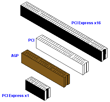
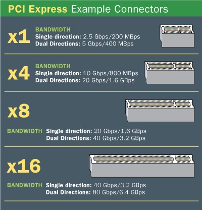
The PCI Express link is built around pairs of serial (1-bit), unidirectional point-to-point connections known as "lanes". This is in sharp contrast to the PCI standard which is a bus-based system in which all the devices share the same bidirectional, 32-bit (or 64-bit), parallel signal path. In PCIe 1.1 (currently the most common version) each lane sends information at a rate of 250 MB/s (250 million bytes per second) in each direction. PCIe 2.0 doubles this, emerging in late 2007, and is found on newer systems such as the Mac Pro. The latest proposed PCIe 3.0 standard will increase this further (scheduled for release around 2010) Each PCIe slot carries either one, two, four, eight, sixteen, or thirty-two lanes of data between the motherboard and the card. Lane counts are written with an x prefix e.g. x1 for a single-lane card and x16 for a sixteen-lane card. Thirty-two lanes of 250 MB/s (PCIe 1.1) give a maximum transfer rate of 8 GB/s (250 MB/s x 32, i.e., 8 billion bytes per second) in each direction. However, the largest size in common use for PCIe 1.1 is x16, giving a transfer rate of 4 GB/s (250 MB/s x 16) in each direction. Putting this into perspective, a single lane for PCIe 1.1 has nearly twice the data rate of normal PCI, a four-lane slot has a transfer rate compared to the fastest version of PCI-X 1.0, and an eight-lane slot has a transfer rate compared to the fastest version of AGP. PCIe slots come in a variety of physically different sizes referred to by the maximum lane count they support, ie. x1, x2, x4, x8, x16, and x32. A PCIe card will fit into a slot of its size or bigger, but not into a smaller PCIe slot. The number of lanes actually connected to a slot may also be less than the number supported by the physical slot size. An example is an x8 slot that actually only runs at x1; these slots will allow any x1, x2, x4 or x8 card to be used, though only running at the x1 speed. This type of socket is described as a 'x8 (x1 mode)' slot, meaning it physically accepts up to x8 cards but only runs at x1 speed. The advantage gained is that a larger range of PCIe cards can still be used without requiring the motherboard hardware to support the full transfer rate - so keeping design and implementation costs down. The number of lanes is "negotiated" during power-up or explicitly during operation. By making the lane count flexible a single standard can provide for the needs of high-bandwidth cards (e.g. graphics cards, 10 Gigabit Ethernet cards, and multiport Gigabit Ethernet cards) while also being economical for less demanding cards. As well as the ordinary expansion cards for desktops and servers, the PCIe electrical interface is used in a variety of other form factors including the ExpressCard laptop expansion card interface. PCIe is also often used to connect integrated peripherals on the motherboard. Specifications of the format are being maintained and developed by a group of more than 900 industry-leading companies called the PCI Special Interest Group (PCI-SIG).

PCI-X
PCI-X was developed jointly by IBM, HP, and Compaq and submitted for approval in 1998. It was designed for servers to: increase the performance of high bandwidth devices such as Gigabit Ethernet, Fibre Channel, and Ultra3 SCSI cards, allow processors to be interconnected in clusters, attempt to codify individual extensions to the standard PCI bus. PCI-X revised the PCI standard by doubling the maximum clock speed (from 66 MHz to 133 MHz)[1] and hence the amount of data exchanged between the computer processor and peripherals. Standard PCI supports up to 64 bits at 66 MHz (though anything above 32 bits at 33 MHz is only seen in high-end systems) and additional bus standards move 32 bits at 66 MHz or 64 bits at 33 MHz. The theoretical maximum amount of data exchanged between the processor and peripherals with PCI-X is 1.06 GB/s, compared to 532 MB/s with standard PCI. PCI-X also improves the fault tolerance of PCI allowing, for example, faulty cards to be reinitialized or taken offline. PCI-X is generally backward-compatible with most cards based on the PCI 2.x[1] or later standard, meaning that, a PCI-X card can be installed in a PCI slot, provided it has the correct voltage keying for the slot and (if inserting into a 32-bit slot) nothing obstructs the overhanging part of the edge connector. Originally the PCI bus was a 5-volt bus. Later, in PCI Revision 2.x, the PCI bus was a dual-voltage interconnect. In 3.0 this was changed to 3.3 volts only. The PCI-X bus is not compatible with the older 5-volt cards but newer 3.3-volt PCI cards will work in a PCI-X slot.[1] Apart from this, PCI and PCI-X cards can generally be intermixed on a PCI-X bus, but the speed will be limited to the speed of the slowest card. For example, a PCI 2.3 device running at 32 bits and 66 MHz on a PCI-X 133-MHz bus will limit the total throughput of the bus to 266 MB/s. To get around this limitation and the voltage compatibility issue, many motherboards have separate PCI-X channels that can be dedicated to different PCI hardware families if needed, allowing for better backward compatibility while maintaining higher total system bandwidth. Versions All PCI-X cards or slots have a 64-bit implementation and vary as follows: 66MHz (added in Rev. 1.0) 100MHz (implement by a 133 MHz adapter on some servers) 133MHz (added in Rev. 1.0) 266MHz (added in Rev. 2.0) 533MHz (added in Rev. 2.0) Slot 66MHz (can be found on older servers) 133MHz (most common on modern servers) 266MHz (rare, being replaced by PCI-e) 533MHz (rare, being replaced by PCI-e) PCI-X 2.0. It adds 266-MHz and 533-MHz variants, yielding roughly 2.15 GB/s and 4.3 GB/s throughputs, respectively. PCI-X 2.0 makes additional protocol revisions that are designed to help system reliability and add Error-correcting codes to the bus to avoid resends.[1] To deal with one of the most common complaints of the PCI-X form factor, the 184-pin connector, 16-bit ports were developed to allow PCI-X to be used in devices with tight space constraints. Similar to PCI-Express, PtP functions were added to allow for devices on the bus to talk to each other without burdening the CPU or bus controller.

PCI
The Peripheral Component Interconnect, or PCI Standard (in practice almost always shortened to PCI), specifies a computer bus for attaching peripheral devices to a computer motherboard. These devices can take any one of the following forms:
* An integrated circuit fitted onto the motherboard itself called a planar device in the PCI specification.
* An expansion card that fits into a socket.
Versions Card
32-bit, 33 MHz (added in Rev. 2.0)
64-bit, 33 MHz (added in Rev. 2.0)
32-bit, 66 MHz (3.3 V only, added in Rev. 2.1)
64-bit, 66 MHz (3.3 V only, added in Rev. 2.1)
Slot
32-bit, 5 V
32-bit, 3.3 V
64-bit, 5 V
64-bit, 3.3 V
PCI provides two separate 32-bit or 64-bit address spaces corresponding to the memory and I/O port address spaces of the x86 processor family. Addresses in these address spaces are assigned by software. A third address space called the PCI Configuration Space, which uses a fixed addressing scheme, allows the software to determine the amount of memory and I/O address space needed by each device. Each device can request up to six areas of memory space or I/O port space via its configuration space registers. Devices are required to follow a protocol so that the interrupt lines can be shared. The PCI bus includes four interrupt lines, all of which are available to each device. PCI bridges (between two PCI buses) map the four interrupt traces on each of their sides in varying ways. Some bridges use a fixed mapping, and in others it is configurable. Later versions of PCI allow (and in the latest versions require) 3.3V slots (keyed differently) on motherboards and allow for cards that are either double keyed for both voltages or even 3.3V only. PCI 2.2 allows for 66 MHz signaling (requires 3.3-volt signaling) (peak transfer rate of 533 MB/s) PCI 2.3 permits the use of 3.3 volt and universal keying but does not allow 5 volt keyed add-in cards. PCI 3.0 is the final official standard of the bus, completely removing 5-volt capability.


